Setting up project and programming our first piece of Rust code onto microcontroller (Part1)
Preparing build environment
After we finished the hardware setup in Part 1 we should have working openocd connection.
Rest of this series of posts will assume stlink or jlink debugger + Blue Pill board. There is variety of clones like these:
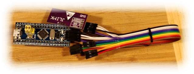
but legality of the software on the clones is at very best dubious. You can also just get a Nucleo board which contains debugger and small eval board all in one
We will also be using template graciously provided by Rust Cortex-M team.
Make sure to use at least Rust 1.53 (tutorial is built on that version) and install cross-compile dependencies of rust and binutils-arm-none-eabi:
 1-> ᛯ rustup target add thumbv6m-none-eabi thumbv7m-none-eabi thumbv7em-none-eabi thumbv7em-none-eabihf
 2info: downloading component 'rust-std' for 'thumbv6m-none-eabi'
 3info: installing component 'rust-std' for 'thumbv6m-none-eabi'
 4info: Defaulting to 500.0 MiB unpack ram
 5info: component 'rust-std' for target 'thumbv7m-none-eabi' is up to date
 6info: component 'rust-std' for target 'thumbv7em-none-eabi' is up to date
 7info: downloading component 'rust-std' for 'thumbv7em-none-eabihf'
 8  4.7 MiB /   4.7 MiB (100 %)   2.2 MiB/s in  2s ETA:  0s
 9info: installing component 'rust-std' for 'thumbv7em-none-eabihf'
10-> ᛯ sudo apt install binutils-arm-none-eabi gdb-multiarch # stuff to debug and extract binaries for the microcontoller
11...
12binutils-arm-none-eabi is already the newest version (2.35.2-2+14+b2).
13gdb-multiarch is already the newest version (10.1-1.7).
14...
and create new project
1$ cargo generate --git https://github.com/rust-embedded/cortex-m-quickstart
2 Project Name: rust-arm
3 Creating project called `rust-arm`...
4 Done! New project created /home/xani/src/my/toolbox/project-templates/rust-arm/rust-arm
Project setup
Our STM32F103 is cortex-M3 CPU so in .cargo/config.toml we need to select it as the target:
1[build]
2# Pick ONE of these compilation targets
3# target = "thumbv6m-none-eabi"        # Cortex-M0 and Cortex-M0+
4target = "thumbv7m-none-eabi"        # Cortex-M3
5...
and in memory.x we need to tell it where is our flash (remember the flash probe 0 openocd command ? That has all of that info) and RAM (RAM usually starts at `0x20000000):
1MEMORY
2{
3
4  FLASH : ORIGIN = 0x08000000, LENGTH = 64K
5  RAM : ORIGIN = 0x20000000, LENGTH = 20K
6}
7
That will tell the compiler on how to map addresses to the given microcontroller. There are some more clever uses of it (like on chips that have more than one RAM regions) but we won't be getting into it now.
At this point cargo build should produce nice debug-ridden binary in target/thumbv7m-none-eabi/debug/rust-arm that weights few times more than what you can even fit on the CPU.
That is ELF-formatted (format used by Linux amoung other) binary that contains code, debug symbols and few other things our embedded CPU doesn't need but the local debugger does.
We have to extract the "raw" binary out of that to have something to program. To do that we will use aforementioned binutils package:
1-> ᛯ arm-none-eabi-objcopy -O binary target/thumbv7m-none-eabi/debug/rust-arm /tmp/rust-arm
2-> ᛯ ls -la /tmp/rust-arm
3-rwxr-xr-x 1 xani xani 2760 07-04 22:14 /tmp/rust-arm
Notice how much smaller it got? It's still a debug build, but the debug info stays on our PC and our microcontroller only gets the unoptimized version of the code. To get the optimized version just do the usual release build.
Note that unlike "normal" builds, there is never a reason to disable debug info as having it on does not increase the size of binary that lands on the microcontroller
That should verify that our whole software chain is working. Now onto writing code
Blinky example
The example code is designed to run on the emulated ARM inside QEMU. Our microcontroller needs a bit more configuration to be happy.
Let's edit Cargo.yaml and add some device-specific dependencies (versions are newest stable as the moment of writing; upgrade if the example have older ones):
 1# cortex-m specific
 2[dependencies]
 3cortex-m = "^0.7.3"     # Low-level access to generic cortex-m processors
 4cortex-m-rt = "^0.6.14" # Minimal runtime
 5embedded-hal = "^0.2.5" # Generic embedded HAL (Hardware Abstraction Layer)
 6panic-halt = "^0.2.0"   # Panic handler
 7
 8# device-specific
 9[dependencies.stm32f1xx-hal]
10# STM32 devices are divided on low, medium and high (memory/flash) density devices. STM32F103 used in Blue Pill is medium
11features = ["stm32f103", "rt", "medium"]
12version = "^0.7.0"
and write some code:
 1#![no_std]
 2#![no_main]
 3
 4use panic_halt as _;
 5
 6use nb::block;
 7
 8use stm32f1xx_hal::{
 9    prelude::*,
10    pac,
11    timer::Timer,
12};
13//use cortex_m_semihosting::hprintln; // It's a surprise tool that will help us later
14use cortex_m_rt::entry;
15use embedded_hal::digital::v2::OutputPin;
Boilerplate to import embedded and stm32 HAL. #![no_std] and #![no_main] is basically us telling the compiler the target lands in embedded land and not in some OS's ELF blob.
embedded_hal::digital::v2::OutputPin is a generic abstraction around output pin.
1#[entry]
2fn main() -> ! {
#[entry] tells the compiler where is the entry point to our code. Now you might ask "we just told it to not have main but it does have main() after all ?" but that's just boilerplate to let the compiler know how to generate code for embedded.
Now that we're in main, we need to set up peripherals:
 1    // Access to peripherals common to Cortex M CPUs
 2    let core_peripherals = cortex_m::Peripherals::take().unwrap();
 3    // Access to peripherals that are device specific
 4    let device_peripherals = pac::Peripherals::take().unwrap();
 5
 6    // RCC is responsible for reset and clock signal configuration
 7    // https://wiki.st.com/stm32mpu/wiki/RCC_internal_peripheral
 8    let mut rcc = device_peripherals.RCC.constrain();
 9
10    // FLASH is responsible for flash config (timing etc.)
11    let mut flash = device_peripherals.FLASH.constrain();
12
13    // freeze the RCC config. This is used so other functions have a base
14    // to calculate say interrupt interval on timer
15    // this is basically "continue working on internal RC clock that you used on boot"
16    let clocks = rcc.cfgr.freeze(&mut flash.acr);
17
18    // Get the GPIOC peripheral
19    let mut gpioc = device_peripherals.GPIOC.split(&mut rcc.apb2);
20
21    // Extract the PC13 (on Blue Pill that's a pin with LED)
22    let mut led = gpioc.pc13.into_push_pull_output(&mut gpioc.crh);
23
24    // Initialize timer based on the system clock, and calculate how much it would need to run with 6 Hz
25    // then start running
26    let mut timer = Timer::syst(core_peripherals.SYST, &clocks).start_count_down(6.hz());
This sets the CPU to run off default 8MHz internal RC clock
at this point we can change the LED state via led.set_low().unwrap()/led.set_high().unwrap()
It needs to be unwrapped because implementation of OutputPin can return Err().
In case of STM32 that's impossible because the implementation is just an atomic write to the register but that abstraction can be used for other devices like say output pin via i2c expander or similar.
 1    // we're not using interrupts here, just busy wait for simplicity
 2    loop {
 3        // wait for our timer to "tick"
 4        block!(timer.wait()).unwrap();
 5        // set a led
 6        led.set_high().unwrap();
 7        // wait again
 8        block!(timer.wait()).unwrap();
 9        // unset a led
10        led.set_low().unwrap();
11        // we're not using XOR because that requires read-modify-write loop but just setting/resetting value have hardware optimization on STM32
12    }
13}
and make it blink!
Here is full sourcecode on github that is inside the project example
We can now reset the CPU to known state (always reset init before writing the flash) and flash our code manually:
 1telnet 127.0.0.1 4444
 2Trying 127.0.0.1...
 3Connected to 127.0.0.1.
 4Escape character is '^]'.
 5Open On-Chip Debugger
 6> program /tmp/rust-arm 0x08000000
 7wrote 2760 bytes from file /tmp/rust-arm in 0.181895s (14.818 KiB/s)
 8
 9> flash verify_image /tmp/rust-arm 0x08000000
10verified 2760 bytes from file /tmp/rust-arm in 0.063410s (42.506 KiB/s)
11
12> reset run
program does reset init then flash write_image as convenient macro.
You can also do program /tmp/rust-arm 0x08000000 verify reset to do reset, flash, verify and run in a single command.
If the LED is blinking, congratulations, you have now landed your first Rust code onto the device!